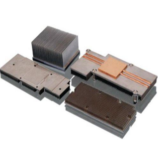
Every heatsink process trades thermal performance against mechanical strength and cost. Extrusion is fast and cheap but limited to profiles a die can pull. Cold forging delivers exceptional stiffness but needs high-tonnage tooling. Skiving sits between them: a cutter slices thin fins directly out of a solid block, so the fins and base are one continuous piece of metal with no bonded interface.
That single fact is why a skived part behaves differently in service. There is no adhesive to degrade, no solder joint to fatigue, and no interface thermal resistance between fin and base. What is left is high fin density in a package that is still light and still machinable to a precise mounting interface.
Table of Contents
- What Is a Skived Fin Heat Sink and How Does It Work?
- Why Skived Fin Heatsinks Are Preferred in High Heat Flux Applications?
- Skived Fin vs. Extruded vs. Cold Forged: How the Processes Compare
- Skived Fin Heat Sink Technical Specifications
- Materials: Why 1060 and 6063 Aluminum Dominate Skiving
- How Fin Height, Thickness, and Pitch Affect Thermal Performance
- Design for Manufacturability: What Skived Fin Geometry Can and Cannot Do
- How Skived Fin Heat Sink Quality Is Verified
- When to Choose a Skived Fin Heat Sink — and What Data to Send
- Frequently Asked Questions About Skived Fin Heat Sinks
1. What Is a Skived Fin Heat Sink and How Does It Work?
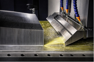
A skived fin heat sink is made by machining thin parallel fins onto a solid metal base. A circular or straight skiving cutter is fed across the workpiece at a controlled depth and feed rate, peeling off thin ribbons of material that leave a precisely spaced row of fins standing on the base.
Because the fins are cut from the base rather than attached to it, the part is monolithic, and every advantage and limitation flows from that. The sequence runs on CNC: a blank of high conductivity aluminum or copper is cut to the rough envelope, the base is machined flat with its mounting interface, the fin field is skived across the top, then the part is cut to length, drilled and tapped, and finished. Because fins and base are cut in the same setup, the fin root is as strong as the base and the part cannot delaminate. Buyers evaluating the wider range can start with the custom heatsink design guide.
2. Why Skived Fin Heatsinks Are Preferred in High Heat Flux Applications?
Skiving raises fin density without introducing an interface — no adhesive, no braze, no solder line between fin and base. That is why a skived part wins when the source is small, the envelope is tight, and the environment is unforgiving.
Thermally, every fin technology increases surface area, but area is not the limiting factor — how much heat crosses a discontinuity is. In a bonded part, fin and base are joined through an adhesive, solder, or braze layer whose resistance adds directly to the total; skiving removes that layer so heat moves from base into fin as one path through a single metal. In a sealed enclosure with weak airflow, that extra conductive surface is often the difference between meeting the target and derating the device.
Mechanically, a monolithic part removes a class of failure mode — no adhesive to soften, no braze fillet to crack, no fin to detach — and weighs less because nothing is added to the base.
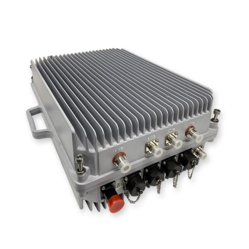
That density is what keeps a high-flux design on air cooling at all, and it is why skived parts still appear in 5G base station and RF amplifier heatsinks where a sealed outdoor cabinet has no airflow to spare. Where flux has already passed the point air can carry, the route changes to a sealed coolant path instead.
3. Skived Fin vs. Extruded vs. Cold Forged: How the Processes Compare
Choosing between the three is less about which is better than about which constraint binds hardest. Skiving cuts fins from a solid block, extrusion pushes a billet through a die, cold forging presses material between dies, and each mechanism imposes its own limits.
| Characteristic | Skived Fin | Extruded | Cold Forged |
|---|---|---|---|
| Fins created by | Machining a solid blank | Pushing through a die | Pressing between dies |
| Fin/base relationship | Monolithic | Monolithic | Monolithic |
| Fin density | Highest; tight pitch | Lower; die-limited | High, closed profiles |
| Cross-section freedom | Free, set by cutter | Fixed by die | Set by die cavities |
| Base thickness | 5–20 mm class | Relatively thin | Thick, rigid |
| Stiffness | Good | Moderate | Highest |
| Volume fit | Low to medium | High volume | Medium to high |
| Lead time | Fast, no die | Die lead time | Die lead time |
Skiving and extrusion are both monolithic but differ in cross-section freedom and volume economics: skiving gives geometry freedom on any single part, extrusion gives cost efficiency only once volume justifies the die. Cold forging wins when stiffness dominates and the profile can be closed. Where density and robustness must both be high, bonded construction enters at the cost of an interface — see cold forged heat sink manufacturing.
4. Skived Fin Heat Sink Technical Specifications
These ranges reflect a capability built around CNC skiving and precision machining — the envelope within which standard designs land. Outside it, a design usually needs re-framing rather than pushing.
| Parameter | Range / Capability |
|---|---|
| Materials | High conductivity aluminum (1060 or 6063); copper |
| Fin height | Machined to design; tall thin fields for density |
| Fin thickness | Set by cutter geometry and material |
| Fin pitch | Adjustable; tight pitch for maximum density |
| Base | Machined to establish flatness and interface |
| Mounting features | CNC-machined holes, slots, tapped interfaces |
| Prototype lead time | Quoted per part; no die is required before the first article |
| Production lead time | Quoted against volume, finishing, and inspection scope |
| Capacity | 150 CNC machines; three plants, 58,000 m², 800+ staff |
| Surface treatment | Anodizing and other protective finishes |
A die-free prototype lets a skived design be evaluated on target hardware before the thermal design freezes — something die-based processes cannot always offer — and the absence of a die also positions skiving as fast-cycle for the mid-volume range. The absence of fixed figures for fin height, thickness, and pitch is itself informative: they are not catalog dimensions, so a quotation is a conversation about geometry.
5. Materials: Why 1060 and 6063 Aluminum Dominate Skiving
Skiving puts unusual demands on a material. The cutter shears a thin chip continuously, generating heat and a lateral load on the fin being formed. An alloy that work-hardens rapidly or lacks ductility will damage the cutter or produce torn fins.
1060 is close to commercially pure, with excellent conductivity for spreading heat through the base and enough ductility to form thin fins without tearing. The trade-off is strength: 1060 is soft, so the part needs adequate base thickness. 6063 adds strength while keeping good conductivity and machinability, and is the more forgiving grade for thinner bases or aggressive fin heights. Copper conducts substantially better than either grade, though the efficient approach is selective — copper where heat enters, aluminum for area.
Geometry is constrained less by the process than by machinability character: softer, purer alloys form finer fins, stronger alloys tolerate thinner bases and taller fins. Production practice is documented on our skiving fin heat sink manufacturing capability page.
6. How Fin Height, Thickness, and Pitch Affect Thermal Performance
Three geometric variables decide how much heat a skived fin field can reject, and they trade against each other and against mechanical survival — treat them as one problem, not three preferences.
Fin thickness is governed by what the cutter can hold. A thicker fin survives handling but occupies more face area and conducts heat a longer distance from base to tip; a thinner fin exposes more surface but is vulnerable under vibration. Parts installed by a person, or travelling in a shock-exposed enclosure, need more thickness than a part fixtured and never touched.
Fin pitch determines density. Tight pitch improves convective performance only if airflow reaches the fins; tight pitch thickens the boundary layer between adjacent fins, and once air stalls inside the field the extra area returns diminishing returns. In natural convection the limit arrives earlier than most designers expect.
Fin height extends area but adds conduction distance and bending moment. A tall fin is a cantilever and its stiffness scales with thickness cubed, which is why high-density designs use a taller, proportionally thicker fin rather than the thinnest the machine could cut. Where airflow is weak, thickness and conductivity are the levers, not area.
7. Design for Manufacturability: What Skived Fin Geometry Can and Cannot Do
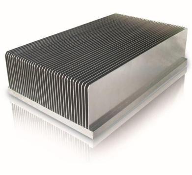
Because skiving cuts fins rather than forming them, geometric rules apply before programming begins. Fin height must stay proportionate to the material’s ability to stand unsupported; any fin that deflects during machining will fail dimensional inspection. Fin spacing must exceed the cutter’s own geometry — a pitch the cutter cannot enter or exit is not a fine-pitch design, it is an unmanufacturable one, and this is the most common cause of a design being returned for revision. Base thickness has a minimum too, because a base too thin to machine flat will bow under the fin field.
Interrupting the fin field for mounting holes is a separate decision: each interruption is a stress concentration and a place where the cutter must stop and resume, costing geometry you could have used for area. Fin field layout should follow the airflow direction rather than fight it, which is free if decided at the design stage.
8. How Skived Fin Heat Sink Quality Is Verified
Because skiving removes material to form the thermal surface, quality control is about verifying what was removed as much as what remains. Incoming material inspection confirms the alloy before cutting begins, which matters more for skiving than most processes because material condition decides whether the cutter produces a clean fin or a torn one. In-process inspection verifies critical dimensions, fin alignment, and surface quality while the part is still on the machine, with general geometry to ISO 2768-m and any dimension affecting thermal contact called out to ASME Y14.5.
Thermal performance testing uses simulation alongside real measurement, recorded against a stated measurement boundary — case-to-ambient and interface-to-ambient are not interchangeable. Simulation establishes that the design logic is right; physical testing establishes that the part achieves it, within days rather than after a die lead time. Final inspection runs on 100% of parts, under ISO 9001, ISO 14001, ISO 45001, QC 080000, IATF 16949, RoHS and REACH — the same certifications Goldconn has held as a Beijing Stock Exchange listed OEM (stock code 8383337) since 2004.
9. When to Choose a Skived Fin Heat Sink — and What Data to Send
Choose skiving when the source is small relative to the envelope, so area must come from density rather than footprint; when airflow is limited or unknown; when vibration, thermal cycling, or handling is present; when weight matters and solid copper is unacceptable; or when the part is too complex for a die but needs a precise machined interface. Choose something else when volume is very high and the geometry is simple, when a closed cross-section is required, when stiffness dominates, or when a certified cross-section exists in a standard profile. The most common mistake is treating skiving as a default upgrade over extrusion: it is a different mechanism with a different cost curve, so the question is which constraint binds hardest.
Buyers comparing options can browse custom thermal solutions.
The case where density stops being enough — a rack drawing hundreds of watts per board — is taken up in microchannel cold plates for AI servers.
The strongest predictor of a precise quotation is a thermal requirement rather than a drawing, because thermal data lets a manufacturer propose geometry that works rather than reproduce a shape. Send the following.
- Thermal duty — heat load in watts and its source, target temperature, ambient conditions
- Airflow situation — natural or forced, with static pressure and flow path direction where known
- Envelope and interface — available space, mounting footprint, hole patterns, orientation
- Material and constraints — a named alloy if required, otherwise the requirement (max conductivity, min density, RoHS), plus mechanical environment and target quantity
To put those details to work, contact our engineering team; we will confirm what skiving can hold, flag the geometry limits, and return a free DFM review with a quotation.
Frequently Asked Questions About Skived Fin Heat Sinks
What materials and lead times?
High thermal conductivity aluminum, commonly 1060 or 6063, and copper; because fins are machined from the base, the material must be ductile enough to form thin fins without tearing. Prototypes need no die before the first article, so the first testable part does not wait on tooling.
Can skived fin heatsinks be anodized?
Yes. Finishing is applied after machining, so the fin field is not exposed to a coating process designed for flat parts.
How does a skived part compare to a bonded one?
A skived part is monolithic, so there is no interface thermal resistance or delamination risk. A bonded part can achieve higher density and greater shape flexibility, but introduces a joining layer that must be qualified for thermal and mechanical reliability.
What is the maximum size?
Overall size is set by the CNC machining envelope and your mounting requirements rather than a catalog limit, which is why a skived part is specified from its thermal requirement, not selected from a profile list.
Request a skived fin heatsink quote. Send us the heat load, the heat source footprint, the envelope, and the airflow situation — by email or by uploading your STEP or PDF drawing — and our engineering team will return a recommended construction, key dimensions, and a verification plan. A free design-for-manufacturability review before tooling is the cheapest point at which to change the design, and typical responses are returned within two working days.