Table of Contents
- Junction Temperature, Not Wattage, Sets LED Luminaire Life
- The Thermal Resistance Chain: Where the Budget Goes
- Fin Area per Watt: Extrusion, Die-Cast, or Skived?
- When the Heatsink Is Also the Chassis: Gasket Faces and Optical Alignment
- Greenhouse Humidity, Cleaning Agents, and Finish Selection
- LED Luminaire Heatsink RFQ: Drawings, Cosmetic Zones, and Test Reports
When a high-power LED luminaire or greenhouse fixture loses lumen output or drifts in colour, the diode is rarely the cause. For OEM lighting engineers and sourcing teams, junction temperature decides whether a fixture meets its published LM-80 and TM-21 projections, and the heatsink must deliver that while holding IP65/IP66 sealing and the project’s component cost, with tooling, piece price, and optical tolerances agreed before release.
1. Junction Temperature, Not Wattage, Sets LED Luminaire Life
High-output luminaires and grow lights drive COB arrays or dense SMD boards at high current, converting much of the input power into waste heat at the p-n junction. Unlike incandescent lamps, LEDs cannot radiate it away as infrared; it must conduct through the substrate and leave through the heatsink.
In sealed fixtures and closed grow rooms, housing ambient rises quickly. If heat cannot move from the diode pads to ambient, junction temperature climbs, phosphor degrades, chromaticity shifts, and output falls for good. Efficiency also drops as junction temperature rises, so a marginal heatsink forces the driver to push more current and make more heat. The penalty reinforces itself and shows as colour shift between fixtures from one batch, not as a clean failure a warranty process can classify.
Two luminaires rated the same wattage can therefore have very different service lives: the label describes input power, while the number that decides life sits inside the diode.
2. The Thermal Resistance Chain: Where the Budget Goes
Before comparing heatsinks, write the chain: junction to solder point, solder point through the board, board to heatsink, heatsink to ambient. Junction temperature is ambient plus heat load times the sum of those resistances, and what is left for the heatsink after the other three take their share is the only number that matters when you choose a profile.
The board often consumes more of that budget than expected. A metal-core PCB conducts through a thin dielectric and spreads well because aluminium sits underneath, while an FR-4 board passes heat through plated vias in a thick, poorly conducting laminate, adding resistance before the heatsink is reached. Switching board type can shift junction temperature more than switching profile.
Spreading matters for the same reason: a small COB on a large plate must move heat sideways through the base before the outer fins help. Internal ambient is the input that gets fudged, because a fixture in an insulated ceiling void or a closed grow room never sees the 25 °C of a test bench, and LM-80 data is collected at specified case temperatures, so a fixture running hotter than that case temperature is no longer described by its TM-21 projection.
3. Fin Area per Watt: Extrusion, Die-Cast, or Skived?
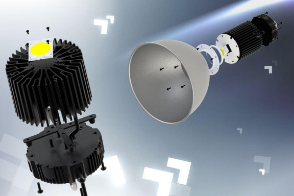
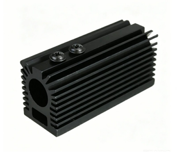
A luminaire heatsink is both structural backbone and radiator: a flat baseplate spreads point-source heat from the PCB or COB holder, and the fin array rejects it into natural convection without opening the sealed optical cavity.
Process choice trades thermal performance against tooling economics. Extrusion is the baseline for linear battens and strip grow lights: a 2D profile gives continuous straight fins cheaply but cannot produce the circular arrays a central COB downlight needs. Complex 3D shapes and an integrated driver compartment favour die casting, at lower conductivity. Skiving peels dense fins from a solid bar, and cold forging forms monolithic pin arrays with no interfacial resistance.
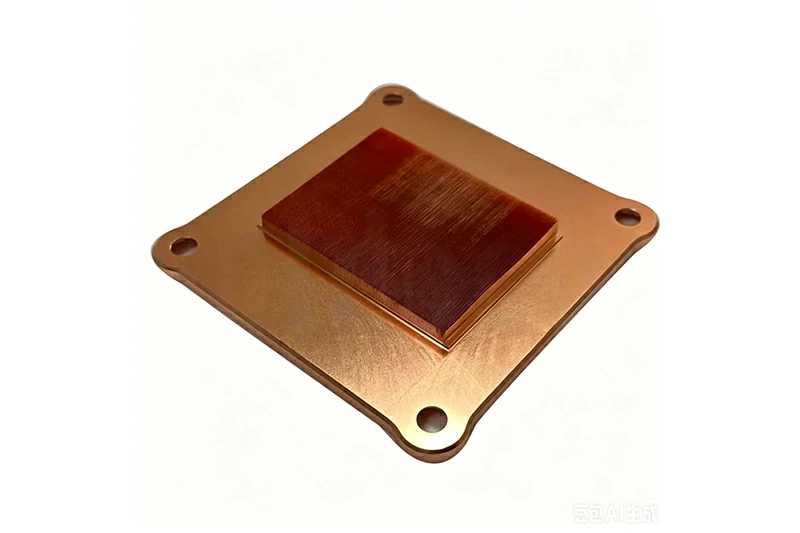
Spacing is a convection decision, not a packing decision. A pitch that works under a fan starves natural convection, because boundary layers on adjacent fins merge and the channel stops moving air, so passive fixtures need wider gaps and vertical channels open at both ends. Under forced air the logic inverts: tighter pitch buys area, provided pressure drop stays inside the fan curve. Thin high-aspect fins in tight housings are covered in the skived fin heat sink design guide.
Goldconn cold-forged pin-fin parts reach about 0.15 °C/W under standard conditions, hold ±0.05 mm tolerances, and cover pin diameters of 0.3-3 mm, pitches of 1.5-10 mm, and heights up to 100 mm. Skiving, die casting, and CNC machining run in the same plants, so a housing and its fin array qualify as one part rather than two suppliers’ parts.
Matching the profile to the housing, not the wattage
The four routes trade tooling cost against fin density and shape freedom; the housing the diode lives in sets the answer.
| Process | Best fit for a luminaire | Where it stops working | Envelope we hold |
|---|---|---|---|
| Extrusion plus CNC | Linear battens, strip grow lights, early builds | Circular or multi-directional arrays around a central COB | 2D profiles with secondary machining of the LED pad |
| Die casting | Fixtures that need a driver compartment and bosses in one part | Thin dense fins; the highest conductivity | ±0.05 mm on critical features |
| Skiving | High fin density inside a tight, sealed housing | Deep three-dimensional outlines and heavy bosses | High-aspect fins cut from the bar, no bond line |
| Cold forging | Central COB clusters where spreading and fin density both matter | Large flat plates with no lateral flux to spread | 0.15 °C/W class parts, ±0.05 mm, pin Ø 0.3-3 mm, pitch 1.5-10 mm, height ≤100 mm |
4. When the Heatsink Is Also the Chassis: Gasket Faces and Optical Alignment
A heatsink that doubles as the chassis must give the gasket a continuous, uniform face. Any bow across the flange opens micro-gaps that admit moisture and dust, and the failure appears only after installation, with the fixture on a ceiling or a greenhouse truss.
The mounting face matters just as much optically. If the LED pad is not flat, tightening screws flexes the PCB, cracking ceramic substrates or tilting LEDs against TIR lenses, and uneven beam angles follow. Holding 0.01 mm per 100 mm keeps clamping pressure uniform across batches, and the edges that locate the diffuser, reflector, and driver cover turn a growing tolerance stack into a visible gap line or an off-centre lens — a cosmetic reject even when thermal performance is fine.
Three drawing redlines that decide whether the fixture passes
- A flatness callout written for thermal reasons alone. The same face that spreads heat also locates the board optically. If it tilts, the beam moves, and the reject is cosmetic although junction temperature is fine.
- A gasket groove cut after the fin field. Second-operation machining on a thin flange bows it, and the leak appears only once the fixture is on a ceiling or a greenhouse truss.
- Cosmetic zones left to the supplier. Unstated visible faces get over-finished at your cost or shipped as-machined, and both come back as a complaint rather than a specification.
5. Greenhouse Humidity, Cleaning Agents, and Finish Selection
Grow houses are the harder case: relative humidity stays high, irrigation water carries dissolved salts, and many operators clean fixtures with acidic or alkaline agents between crops. Wrought 1070 aluminium forges and conducts best but needs careful fastener bosses; 6061 and 6063 extrusions are stronger and cheaper to tool but limited to 2D fins; cast alloys integrate ribs and ears at lower conductivity; copper carries the highest flux at the highest weight and galvanic risk. Anodising protects external fins and raises emissivity, while powder coating adds chemical resistance.
Two rules keep this simple: protect the surfaces that see moisture and chemicals, and leave bare the surfaces that must conduct. Do not coat fin fields unless the thermal penalty has been calculated, because a coating thick enough to resist cleaning agents also insulates the fins it covers.
6. LED Luminaire Heatsink RFQ: Drawings, Cosmetic Zones, and Test Reports
A production RFQ needs 3D CAD plus toleranced 2D drawings defining critical-to-quality dimensions, datums, gasket grooves, masked mounting zones, and flatness at 0.01 mm per 100 mm, and the custom heatsink design and manufacturing guide shows how to write callouts a shop can hold. Add dissipation wattage, maximum junction temperature, ambient, and hanging constraints, and say how flatness and coating thickness will be inspected.
Lighting adds one input other enquiries rarely carry: cosmetic definition. Say which faces are visible and where a scratch becomes a reject, otherwise a supplier either over-finishes everything and charges for it or under-finishes the face the customer sees.
Documents that travel with the parts
- Flatness on the LED pad and gasket flange, against one datum, reported with the first article.
- Coating thickness records by zone, because a coating thick enough for a grow house also insulates the fins.
- 100% inspection on the mounting face and the fixing pattern.
- A salt-spray or humidity report wherever the fixture is bound for a greenhouse or coast.
The certificate covers the process. These four documents describe the parts that leave the plant. On volume, the unit-cost savings, thermal headroom, and structural consolidation of custom forming outweigh the tooling spend, while low-power linear battens and indoor strip fixtures stay cheaper on standard extrusion plus secondary milling.
Goldconn has made metal parts since 2004 and is listed on the Beijing Stock Exchange (code 8383337). Three plants cover about 58,000 m² with 800+ people and 300+ machines, 150+ of them CNC centres. IATF 16949 has been held since 2009 alongside ISO 9001, ISO 14001, ISO 45001, QC080000, and RoHS; cold forging, die casting, skiving, and CNC machining run in-house under thermal management capabilities.
To weigh those options on your own luminaire, contact our engineering team with the LED load, housing constraints, and annual volume; a free DFM review and quotation follow.
Frequently Asked Questions
Does a bigger heatsink always extend LED life?
No. Extra fin area helps only if heat can reach it: a large plate bolted to a warped face still runs hot at the junction, and over-finishing visible surfaces adds insulation where conduction was needed.
Why does output drop after two years when the datasheet promises far longer?
The datasheet assumes a junction temperature the fixture may never reach. Driver heat, blocked vents, high room temperature, or moisture let past a compressed gasket can push the real operating point beyond the tested condition.
What is the minimum data set for an LED heatsink quotation?
Dissipation wattage, LED package and count, maximum junction temperature, ambient and mounting orientation, board outline, fixing pattern, cosmetic zones, and annual volume.
Reviewed by the Goldconn thermal engineering team. The process limits quoted in this guide come from parts produced on our own cold forging, die casting, skiving, stamping, and CNC lines, and the photographs show components from current production.