Table of Contents
- Power Density, Not Total Wattage, Defines a Consumer Heatsink
- Touch Temperature and IEC 62368-1: The Safety Limit That Shapes Design
- Stamped, Extruded, or Die-Cast: Choosing by Annual Volume and Wall Thickness
- Cosmetic Anodizing and Colour Consistency on Visible Parts
- Thermal Interface in a Sub-Millimetre Gap
- Design for Assembly: Clips, Spring Contacts, and Screwless Mounting
- Consumer Heatsink RFQ: What to Send for a 24-Hour Review
When a high-density USB-PD charger or slim power supply throttles under load, users feel the heat on the casing before they notice a performance drop. For OEM product engineers and sourcing teams, dissipating that heat inside a very thin enclosure means balancing unit cost against strict cosmetic standards, with a partner who holds dimensions and surface quality at scale rather than in a lab.
1. Power Density, Not Total Wattage, Defines a Consumer Heatsink
Slim laptops, streaming boxes, high-wattage chargers, and external power supplies keep shrinking without giving up electrical performance. Power density rises inside sealed housings, and most of these devices are fanless, so heat cannot leave by forced air.
Energy must instead conduct from switches, transformers, and rectifiers into the enclosure or an internal heatsink and leave by natural convection. Push more watts through a smaller volume and local flux spikes, which is why a 65 W charger can be harder to cool than a 300 W supply: the small unit has almost no surface and no airflow.
That inversion is why wattage comparisons mislead. What matters is watts per unit of available surface, how many interfaces the heat crosses, and whether the enclosure is allowed to get warm. Divide the affordable temperature rise by the watts to get a resistance budget in °C/W, subtract the die, the interface, and any spreader, and what remains is what the heatsink must deliver.
2. Touch Temperature and IEC 62368-1: The Safety Limit That Shapes Design
In consumer products the casing is part of the experience and also a safety surface. IEC 62368-1 sets accessible-surface limits that depend on the material, the part touched, and how long contact lasts, so a metal chassis and a plastic shell cannot be treated the same way at the same temperature.
Metal conducts to the hand quickly, so a thermally excellent metal heatsink can fail a touch-temperature requirement while a plastic housing at the same internal temperature passes. Designers therefore choose between dumping heat into a visible metal surface and risking the limit, or keeping heat inside and routing it out through vents, a rear panel, or an internal sink the user never touches.
That decision drives the architecture: whether the heatsink is exposed or hidden, whether the enclosure needs venting, and how much margin the design carries at worst-case ambient rather than on a bench. It also makes the enclosure part of the thermal path: plastic conducts poorly, so a sealed plastic box relies on the board and internal air alone, while a die-cast or sheet-metal case carries heat to the surface and becomes the cheapest thermal upgrade in many designs.
3. Stamped, Extruded, or Die-Cast: Choosing by Annual Volume and Wall Thickness
A thin-profile heatsink wins by maximising surface area inside the space available: a thin base spreads point heat across the footprint, and closely spaced fins form convective channels that work in constrained internal air.
Process follows volume and geometry. Extrusion is the baseline for linear supplies: a 2D profile gives continuous thin fins at low tooling cost and conducts well. Complex 3D contours and variable wall thickness suit high-pressure die casting, though casting alloys conduct less. Progressive stamping produces lightweight fin stacks at high speed, at the cost of a separate base interface. Where dense pin arrays are needed under high-flux components, cold forging forms a monolithic part with no interface resistance, reaching about 0.15 °C/W depending on boundary conditions.
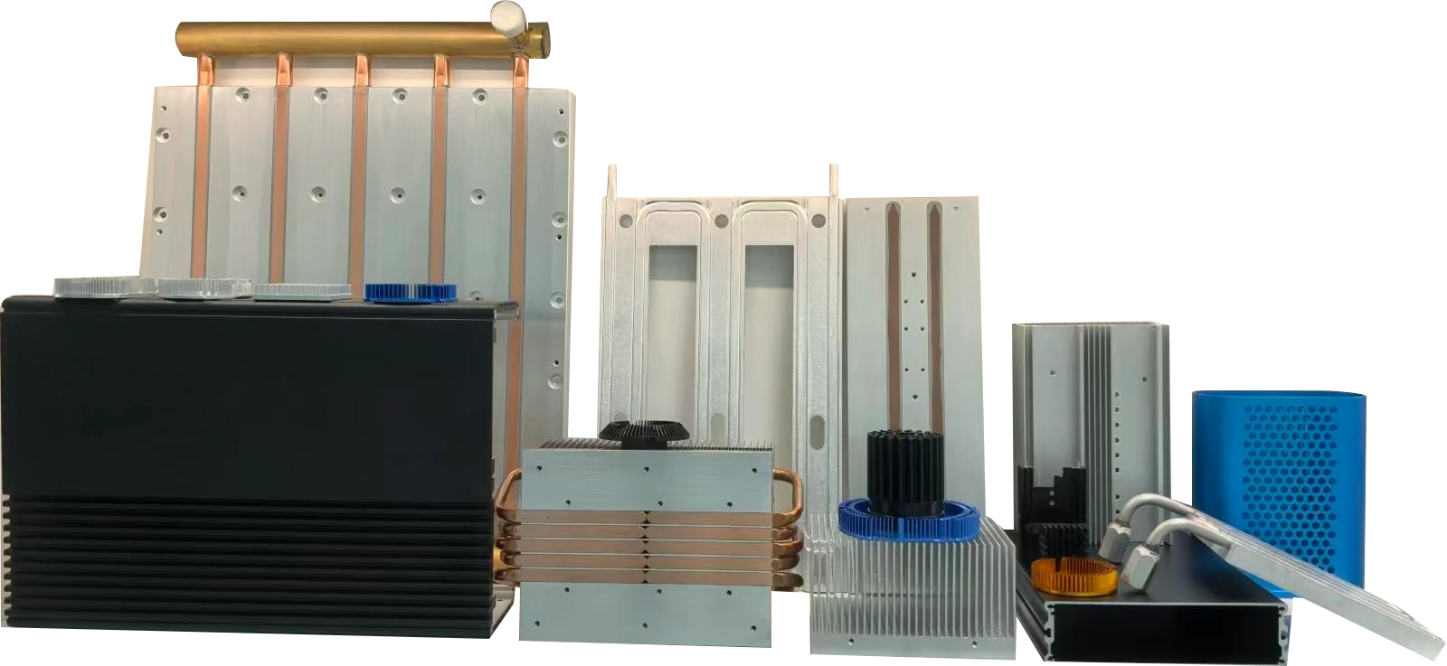
Thick blocks add weight and break dimensional limits, while optimised thin profiles dissipate at low mass. Where a stamped stack still needs lateral spreading, the base and folding options are covered in the sheet metal stamping overview.
What each process can amortise
Consumer programmes are decided by annual volume first and flux second, so the table is ordered by what the tooling has time to pay back. A progressive die, an extrusion profile, or a casting tool is a fixed cost that only makes sense divided across volume, so the honest comparison is cost per part at forecast, not tooling price.
| Process | Best fit for a consumer product | Failure boundary | Envelope we hold |
|---|---|---|---|
| Stamping plus folding | High volume, thin walls, integral clips and EMI screens | Thick sections and tall fin fields | ±0.05 mm on critical features, progressive tooling |
| Extrusion plus CNC | Moderate volume, straight fins, a visible anodised face | Round or omnidirectional flow around a central source | 2D profiles with secondary machining |
| Die casting | Complex cosmetics, integrated bosses, a one-piece housing | Thin walls and the highest conductivity | 180-1250 T presses, ±0.05 mm on critical features |
| Cold forging | A small, very hot source in a shallow envelope | Large flat parts where a pin field adds nothing | 0.15 °C/W class parts, pin Ø 0.3-3 mm, pitch 1.5-10 mm, height ≤100 mm |
4. Cosmetic Anodizing and Colour Consistency on Visible Parts
In consumer products the heatsink is often visible through a grille or forms part of the housing, so thermal performance has to coexist with cosmetic control. Die lines, oil stains, and uneven anodising tones trigger rejection and damage the brand.
Uniform appearance comes from controlled deburring, etching, bead blasting, and decorative anodising. Coating thickness must raise emissivity and corrosion resistance without becoming a thermal barrier, and colour must hold batch to batch so metal parts match adjacent moulded bezels and glass; metal-to-plastic matching is the usual reason a cosmetic sample fails. Alloy and finish work as a pair: 1070 forges and conducts best but needs careful bosses, 6061 and 6063 extrusions are stronger and cheaper to tool but limited to 2D fins, die castings integrate ribs and housings at lower conductivity, stamped steel or aluminium is light and cheap at volume with weaker spreading, anodising adds corrosion and wear resistance at the cost of an insulating layer, and laser marking carries branding provided surface prep is controlled.
5. Thermal Interface in a Sub-Millimetre Gap
In a slim product the interface is where most of the margin disappears: two surfaces that look flat are rough at the micron scale, and the trapped air insulates far better than metal. The interface material displaces that air, and its thickness is set by how flat the parts are.
Grease gives the lowest resistance per unit thickness but needs controlled dispensing and a flat, rigid base. A gap pad tolerates larger, less uniform gaps at higher resistance. Graphite sheet spreads heat laterally but conducts poorly through its thickness, so it belongs over a hot spot rather than between die and sink.
Two failure modes are worth designing against. Pump-out happens when cycling squeezes grease away from the contact area and shows as a slow temperature rise over the first year; dry-out happens in high-temperature products where the carrier evaporates. Both argue for a pad in consumer goods where nobody will re-apply paste, and for a flat base that lets a thin layer work.
6. Design for Assembly: Clips, Spring Contacts, and Screwless Mounting
A heatsink that needs four screws and a driver is expensive at consumer volumes, so the mounting method matters as much as the metal. Spring clips, push rivets, and screwless retention all remove labour, but each changes the pressure distribution across the interface.
Clip pressure is easy to get wrong: a clip bearing on the centre of a thin base bows it away from the component at the edges, opening the very gap the design meant to close. Both that and an uneven clip pass a visual check and appear later as field returns in one batch.
The fix is to design retention and base stiffness together: specify where force is applied, how much deflection the base can take without losing flatness, and what the interface material is. If the part is also structural, add the assembly sequence to the drawing review, because a heatsink that only fits in one order creates a line-side problem no tolerance can solve.
Three drawing redlines that decide the interface
- A flatness number on the heatsink but not on the housing that clamps it. Two bowed parts make a thick pad, and that pad is where the margin goes.
- A clip drawn at the centre of a thin base. The clip bows the plate, lifts the edges, and opens the interface where the hottest component sits.
- Anodising over the contact patch. The colour stays consistent and contact resistance does not; mask the patch or finish-machine it after treatment.
7. Consumer Heatsink RFQ: What to Send for a 24-Hour Review
Send 3D CAD plus toleranced 2D drawings defining critical dimensions, datums, cosmetic face designations, and mounting flatness such as 0.01 mm per 100 mm. Add dissipation wattage, maximum semiconductor temperature, enclosure volume, ambient, annual volume, and the touch-temperature surfaces the safety standard applies to; the last two are routinely missing and change the recommended route. At high volume, unit-cost savings, weight reduction, and thermal headroom outweigh the tooling spend, so teams comparing geometry can read the custom heatsink design and manufacturing guide before freezing enclosure drawings.
What you can hold us to
- Flatness on the base and the face it contacts, against one datum, reported with the first article.
- Coating and anodising thickness records by zone, because the visible face and the contact patch are treated differently.
- 100% inspection on the contact patch, the fixing points, and the cosmetic faces named in the drawing.
- A colour sample pulled from a production run rather than a lab coupon, since metal-to-plastic matching is where cosmetic programmes fail.
Certificates describe a system. These four documents describe the parts in the box.
Goldconn began metal manufacturing in 2004 and trades on the Beijing Stock Exchange under code 8383337. Three bases of about 58,000 m², 800+ staff, and 300+ machines, 150+ of them CNC centres, support its OEM programmes. IATF 16949 has been held since 2009 with ISO 9001, ISO 14001, ISO 45001, QC080000, and RoHS; tooling, extrusion, die casting, stamping, cold forging, and CNC machining run in-house under thermal management capabilities, with a free DFM review in two working days and a quotation within 24 hours.
To lock those decisions down on your own product, contact our engineering team with the board layout, target wall thickness, and annual volume.
Frequently Asked Questions
Why is a 65 W charger sometimes harder to cool than a 300 W supply?
Because the constraint is surface area and airflow, not total power: the small unit has almost no external surface and no fan, so the same heat per square centimetre produces a much larger rise.
Does a metal heatsink always cool better than a plastic housing?
For the component, usually yes, because metal spreads and conducts. For the user, no: metal reaches the touch limit sooner, so heat may have to leave through a hidden path instead.
Which standards apply to a consumer heatsink?
RoHS and REACH for substances, and IEC 62368-1 for the safety of the finished product, including accessible-surface temperatures. Material traceability has to survive the whole product life.
Reviewed by the Goldconn thermal engineering team. The process limits quoted in this guide come from parts produced on our own cold forging, die casting, skiving, stamping, and CNC lines, and the photographs show components from current production.