EV thermal designs rarely fail in simulation; they fail at the mechanical boundary where silicon meets aluminium under thermal cycling and road vibration. Specifying cooling hardware for inverters, onboard chargers, and motor drives comes down to controlling spreading resistance, baseplate flatness, and tooling lead time against automotive quality standards.
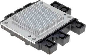
Table of Contents
- The Three Heat Sources in EV Powertrains: Traction Inverter, Onboard Charger, and Motor Drive
- Why EV Power Electronics Need High-Density Pin Fins
- Cold-Forged Pin Fins vs. Extruded and Bonded-Fin Heatsinks
- Automotive-Grade Reliability: IATF 16949, Vibration Fatigue, and Thermal Cycling
- Thermal Resistance and the Interface: Flatness, TIM, and Mounting
- Manufacturing, Flatness Control, and 100% Inspection
- How to Evaluate and What to Send: Sourcing EV Power Electronics Heatsinks
- Conclusion
1. The Three Heat Sources in EV Powertrains: Traction Inverter, Onboard Charger, and Motor Drive
Each powertrain carries three conversion subsystems with different thermal loads. The traction inverter turns DC into three-phase AC for the motor and spikes during acceleration and regenerative braking. The onboard charger (OBC) converts grid AC to DC, running continuous loads for hours while parked with little airflow. Auxiliary drives add high-frequency vibration from the gearbox and road. One platform must therefore handle peak transient dissipation, steady-state endurance, and mechanical durability at once.
SiC MOSFETs versus IGBTs. SiC devices switch faster and cut switching losses, shrinking the inverter. But a SiC die is far smaller than an equivalent IGBT die, so the same heat load lands on a smaller footprint and local flux rises sharply — demanding higher-conductivity material, denser pins, and tighter mounting flatness.
2. Why EV Power Electronics Need High-Density Pin Fins
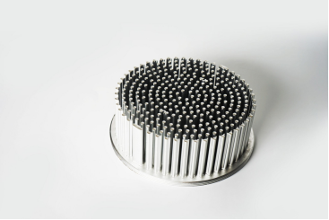
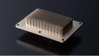
Straight fins hit a ceiling once flow must turn around manifolds, capacitors, and busbars. Staggered cylindrical or elliptical pin arrays break up laminar flow, generate wake turbulence, and accept flow from almost any inlet angle.
Density is a trade-off: pins packed too closely restrict flow, and once pressure drop exceeds fan or pump capacity, mass flow — and cooling — collapses. Pin diameter and spacing must be tuned to add turbulence without overloading the pump. Matching manufacturable pin aspect ratios to a real flow budget is covered in the cold-forged pin-fin heatsink guide.
Why bonded fins add risk. Where tall fins and narrow gaps exceed extrusion limits, designs often slot fins into a grooved base with epoxy, solder, or brazing. Those layers add a boundary where voids raise parasitic resistance, and differential expansion under vibration and temperature swing degrades the joint over vehicle life.
3. Cold-Forged Pin Fins vs. Extruded and Bonded-Fin Heatsinks
Process choice weighs conductivity, geometric freedom, structural integrity, and tooling economics across the program.
| Design consideration | Cold-forged pin fins | Extruded heatsinks | Bonded-fin heatsinks |
|---|---|---|---|
| Base-to-fin structure | Monolithic; pins and base from one slug | Monolithic 2D linear profile | Multi-part, joined by epoxy, solder, or brazing |
| Fin geometry and flow | 3D cylindrical, elliptical, or custom pins; omnidirectional | Straight fins or simple cross-cuts; unidirectional | Linear plates in base grooves; unidirectional |
| Material conductivity | Pure aluminium (1070) and copper alloys | Usually 6061 or 6063 aluminium | Allows mixed materials |
| Interfacial resistance | Zero at pin roots | Zero at fin roots | Added across the joint |
| Vibration and shock | High; no delamination risk | High; single-piece section | Moderate to low; joint-dependent |
| Tooling and unit cost | Moderate-to-high die cost; competitive at volume | Low die cost; lowest for 2D | Moderate tooling; higher assembly cost |
Cold forging presses a solid billet into a closed die at room temperature, giving zero interfacial resistance and no internal porosity. Goldconn cold-forged pin-fin heatsinks reach about 0.15 °C/W depending on package conditions, hold ±0.05 mm tolerances, and support pin diameters of 0.3–3 mm, pitches of 1.5–10 mm, and heights up to 100 mm.
When other routes win. An auxiliary controller with modest flux and linear airflow is cheapest on standard extrusion. Skived fins — peeled from solid bar — suit medium volumes without forging die investment. Sealed liquid-cooled inverters may call for a liquid cold plate that integrates internal channels with forged or machined turbulators.
4. Automotive-Grade Reliability: IATF 16949, Vibration Fatigue, and Thermal Cycling
Parts must survive sub-zero starts, under-hood soak, and constant road shock.
Process control. IATF 16949 is the baseline for defect prevention and traceability; sourcing teams pair it with VDA 6.3 audits to check how billet batches, forging parameters, and CNC tool wear are controlled. PPAP proves the supplier can hold critical dimensions at volume.
Vibration and shock. Units near the drive unit see multi-axis vibration validated to standards such as ISO 16750. Root micro-cracks or brittle joints can fracture fins and block cooling loops; monolithic forging keeps grain flow continuous, and rigid bosses prevent bolt preload relaxation and TIM pump-out.
Thermal and power cycling. Fast charging and repeated acceleration load the assembly from outside and inside. Because SiC dies, substrates, and aluminium expand differently, shear stress builds at the interface; correct temper, baseplate thickness, and stress-relieved machining prevent warping.
5. Thermal Resistance and the Interface: Flatness, TIM, and Mounting
In most assemblies the largest resistance is not the heatsink body but the contact interface under the module baseplate.
Flatness. Even a freshly machined face carries micro-peaks over a macroscopic bow, trapping insulating air. Holding 0.01 mm per 100 mm on contact zones cuts bond-line thickness, contact resistance, and hot spots beneath SiC or IGBT dies. Teams setting drawing callouts can check the custom heatsink design and manufacturing guide first.
TIM selection. Greases, phase-change materials, and gap pads displace air, but their conductivity is far below solid metal. Poor flatness forces thicker compressible pads to absorb tolerance stack-up, which erodes the margin dense pins just bought.
Mounting validation. Contact resistance depends on flatness, roughness, fastener placement, and torque sequence. Screws spaced too far apart concentrate clamp load at the holes while the centre domes upward; verify uniform pressure with pressure-sensitive film and TIM footprints after disassembly.
6. Manufacturing, Flatness Control, and 100% Inspection
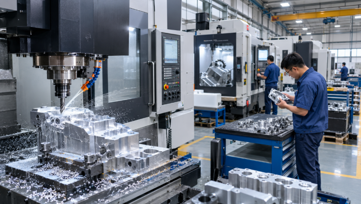
Heavy forging leaves residual stress in the billet, and machining the mounting face releases it as slight spring-back. A manufacturer that owns tool design, cold forging, CNC machining, stamping, die casting, laser cutting, and skiving can engineer preforms and fixtures as one system — the integration described under thermal management capabilities.
Holding 0.01 mm per 100 mm alongside ±0.05 mm general tolerances needs rigid fixtures and CMM verification. 100% inspection on critical features — mounting flatness and sealing grooves — keeps out-of-spec parts off automated inverter lines.
Goldconn, founded in 2004 and listed on the Beijing Stock Exchange (code 8383337), operates three plants of about 58,000 m² with 800+ staff and 300+ machines including 150+ CNC centres. It has held IATF 16949 since 2009 with ISO 9001, ISO 14001, ISO 45001, QC080000, and RoHS, and offers a free DFM review in two working days with a 24-hour quotation.
7. How to Evaluate and What to Send: Sourcing EV Power Electronics Heatsinks
Five audit points. Confirm the IATF 16949 certificate covers the actual forging and CNC sites; verify in-house die-making and CNC capacity; check how 0.01 mm per 100 mm flatness is gauged across batches; require lot traceability from billet to shipment; and test whether DFM flags pin-aspect-ratio or sealing-groove risk before tooling steel is cut.
RFQ package. Send 3D STEP plus 2D PDFs marking critical tolerances and flatness zones, alloy and finish specifications, thermal boundary conditions (dissipation, footprint, flow rate, pressure-drop limit), quality requirements (PPAP level, inspection features, leak-test parameters), and prototype plus annual volume with SOP targets.
Why integration matters. Splitting forging, CNC, and plating across shops adds transit, handling risk, and split accountability when flatness drifts. One owner of presses, CNC centres, and metrology shortens corrective action.
When custom is wrong. Forging dies rarely pay off for lab prototypes or low-volume specialty vehicles. Modifying a standard extrusion, using a skived block, or machining from bar avoids tooling cost and speeds bench testing.
8. Conclusion
Sourcing EV heatsinks means treating thermal design and mechanical manufacturing as one problem. Dense pin fins, monolithic forging, and 0.01 mm per 100 mm flatness only deliver simulated performance when backed by integrated CNC machining, 100% critical-feature inspection, and disciplined IATF 16949 control. Send your models, heat-load data, and flatness callouts for review before cutting production tooling.
Goldconn’s engineers can run that review with you: contact our engineering team with the models and heat-load data, and you will receive a free DFM review within two working days plus a formal quotation.
Frequently Asked Questions
What is the best heatsink process for EV power electronics?
It depends on local flux, cooling medium, and volume. Cold forging suits dense 3D pins in liquid-cooled or omnidirectional air-cooled inverters; extrusion suits low-power linear airflow; skiving fits medium volumes.
Are cold-forged pin-fin heatsinks suitable for traction inverters and OBCs?
Yes. Forged arrays project into inverter coolant jackets or maximise convection inside compact OBC housings while resisting chassis vibration.
Does SiC always require a different heatsink from IGBT?
Not a new concept, but smaller SiC dies concentrate flux. Engineers respond with higher-conductivity alloys, denser pins beneath the die, and tighter flatness.
Why is mounting-surface flatness important?
It sets the gap between module and baseplate. At 0.01 mm per 100 mm, insulating air pockets disappear, thin TIM can be used, and contact resistance drops.
Is IATF 16949 enough to qualify a supplier?
No. The certificate only proves a quality framework exists; audit in-house forging and CNC capacity, CMM metrology, flatness control, and PPAP on comparable parts.
When should an OEM choose a custom heatsink?
When standard extrusions cannot fit the envelope or handle peak flux. From B-sample to serial production, custom cold-forged or machined designs cut weight and unit cost.