Selecting an IGBT module or industrial inverter heatsink means balancing thermal resistance, pin-fin geometry, interface quality, airflow, and long-term reliability against manufacturing and production constraints.
Table of Contents
- Why IGBT Modules and Industrial Inverters Are Thermally Demanding
- How Pin-Fin Density Affects Thermal Resistance
- Mounting Interface and the Bolted-Joint Thermal Budget
- Thermal Cycling and Reliability
- Cold-Forged Pin Fins Combined With a Die-Cast Integrated Housing
- Supplier Evaluation Checklist for an IGBT Heatsink
- RFQ Data Sheet: Six Items to Provide
- Cold-Forged Pin Fins as a Manufacturing Differentiator
- Cost Considerations: When Does Cold Forging Make Sense?
1. Why IGBT Modules and Industrial Inverters Are Thermally Demanding
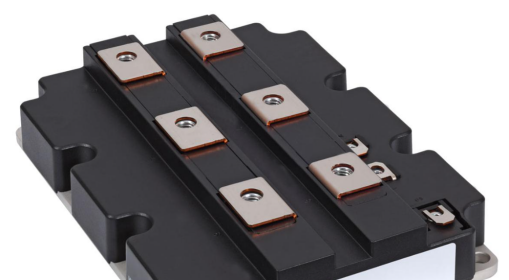
IGBT modules generate heat through switching and conduction losses. Three factors drive heatsink design: power density, switching losses, and junction-temperature limits.
Compact inverters concentrate load inside a small enclosure, so the resistance of the whole cooling path matters. Actual dissipation depends on switching frequency, current, voltage, and device characteristics — size the heatsink from calculated or measured losses, not from the inverter’s electrical rating.
Many industrial semiconductors are rated near 150 °C at the junction (device-specific). Running at that limit leaves no margin for transients, ambient swings, or ageing. Heat crosses substrate, interface material, mounting interface, base, and air; each stage adds resistance, and the goal is minimum junction-to-ambient resistance within acceptable size, weight, cost, and reliability. The custom heatsink design and manufacturing guide is a useful starting point before tooling is committed.
2. How Pin-Fin Density Affects Thermal Resistance
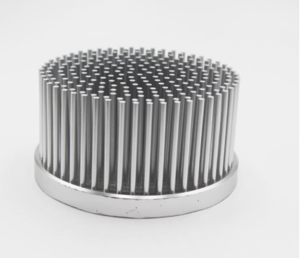
Pin performance depends on count, thickness, height, spacing, and airflow direction. Cold-forged pin fins pack dense surface into a compact footprint, and their multidirectional geometry tolerates airflow from changing angles.
Density is not free. More surface helps, but tightly spaced pins raise pressure drop and can choke airflow, especially in natural convection.
| Design parameter | Potential thermal benefit | Engineering consideration |
|---|---|---|
| Higher pin density | More heat-transfer surface in a given footprint | Excessive density can restrict airflow |
| Greater pin height | More exposed surface | Taller pins raise pressure drop and structural demand |
| Smaller pin thickness | More pins in a compact area | Mechanical strength and feasibility must be checked |
| Wider pin spacing | Better airflow passage | Fewer pins fit the available area |
| Optimized pin arrangement | Improved airflow distribution | Depends on fan direction and enclosure geometry |
Goldconn’s cold-forging capability includes pin-fin thermal resistance of approximately 0.15 °C/W, pin thicknesses of 0.3–3 mm, pitches of 1.5–10 mm, and fin heights up to 100 mm. These are capability benchmarks, not guaranteed results: actual resistance depends on geometry, base size, airflow, test conditions, and measurement method. For illustration, 0.15 °C/W corresponds to a 30 °C rise at 200 W — meaningful only when conditions match the application.
3. Mounting Interface and the Bolted-Joint Thermal Budget
A good heatsink underperforms on a poor interface. Resistance between module and heatsink depends on interface material, flatness, contact pressure, surface condition, hole arrangement, and assembly consistency.
Even flat-looking metal touches only at microscopic high points, and trapped air conducts badly, so a thermal interface material (TIM) fills the gaps. Mounting must deliver enough uniform pressure without exceeding the module maker’s mechanical limits: uneven bolt loading, excess torque, distortion, or a wrong TIM creates local bottlenecks.
Goldconn supports machined interface flatness of 0.01 mm per 100 mm, which controls geometric variation across the contact area; final performance still depends on mounting design and assembly. Treat the interface as part of the thermal budget instead of taking the heatsink’s rated resistance as the whole solution.
For illustration, allocating about 0.20 °C/W to the interface and bolted path gives a 40 °C difference at 200 W. This is an illustrative example, not a Goldconn specification or a universal limit. Drawings should state interface requirements, hole locations, torque, and TIM.
4. Thermal Cycling and Reliability
Inverters cycle through startup, shutdown, load variation, switching, and ambient change. Repeated cycling fatigues interconnects, solder layers, TIM, and mechanical joints.
Materials with different coefficients of thermal expansion build stress during cycling, causing solder fatigue, interface degradation, or loss of contact pressure. Heatsink mass, geometry, and mounting affect assembly stress, so evaluate base temperature distribution, mounting stiffness, and bolt locations, then validate under representative conditions. CFD assesses airflow and heat transfer, FEA assesses deformation and stress — neither replaces physical testing.
Quality systems matter: IATF 16949 gives an automotive framework and PPAP demonstrates capability. Goldconn has held IATF 16949 since 2009, with ISO 9001, ISO 14001, ISO 45001, QC 080000, and RoHS. Buyers should confirm certification scope and customer-specific validation.
5. Cold-Forged Pin Fins Combined With a Die-Cast Integrated Housing
An inverter heatsink usually lives inside a larger assembly where brackets, walls, cable interfaces, and cooling passages affect performance and packaging.
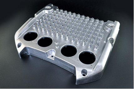
Combining cold-forged pin fins with a die-cast housing suits designs needing controlled pin geometry plus integrated mechanical features; die casting produces shapes that would otherwise need extra machining or separate parts. Goldconn performs both in-house, with cold-forging tolerances of ±0.05 mm, pin thickness of 0.3–3 mm, pitches of 1.5–10 mm, and heights up to 100 mm — applicability confirmed against the drawing and inspection requirements.
One organisation coordinating several processes improves thermal-to-mechanical communication, but integration is not always best: separate parts can suit serviceability, material, or tooling. The cold forging process is worth evaluating when pin geometry, compact packaging, and integration matter — decided on resistance, structure, economics, and validated capability, not on process preference.
6. Supplier Evaluation Checklist for an IGBT Heatsink
Ask for evidence, not attractive dimensions or pricing:
- Measured thermal resistance with test conditions — heat input, airflow, ambient, mounting, measurement points. Values without conditions cannot be compared.
- Simulation evidence (CFD, FEA, validation data) that matches your enclosure and cooling configuration.
- Interface flatness: required value, measurement method, datums, and inspection criteria, plus results or an inspection plan.
- Production traceability: how lots, inspections, nonconformances, and changes to material, tooling, and process are controlled.
- Machining scope: which features are made in-house and which are outsourced. Goldconn states 0.01 mm per 100 mm interface flatness and ±0.05 mm cold-forging tolerance — different specifications, so confirm which applies.
- Tool and mould life: an estimate with assumptions and maintenance needs, since tooling drives investment and long-term cost.
- Quality credentials and scope (IATF 16949, ISO 9001/14001/45001, QC 080000, RoHS). Certification alone does not prove thermal performance.
7. RFQ Data Sheet: Six Items to Provide
A clear RFQ lets the manufacturer judge feasibility, pick a process, and flag missing data early.
| RFQ item | Information to provide | Why it matters |
|---|---|---|
| 1. Power dissipation | Pdiss in watts per module or heatsink, with operating conditions | Establishes the real thermal load |
| 2. Junction-temperature target | Maximum design junction temperature and margin | Defines the performance objective |
| 3. Cooling conditions | Natural convection or forced airflow, in LFM where applicable | Determines fin geometry and airflow assumptions |
| 4. Ambient conditions | Expected ambient temperature and environment | Sets the available temperature-rise budget |
| 5. Mechanical envelope | Length, width, height, weight limits, available space | Limits feasible geometry |
| 6. Mounting and interface | Module footprint, hole pattern, TIM, flatness, assembly constraints | Ensures mechanical fit and contact consistency |
Add the module datasheet, 2D/3D CAD, and any simulation or test data. Early-stage designs can start with what exists; the supplier should state assumptions and gaps. A well-defined RFQ also makes quotes comparable.
8. Cold-Forged Pin Fins as a Manufacturing Differentiator
Cold-forged pin fins are not exclusive to any supplier; value comes from design flexibility, process control, and coordination with other operations. Vertical integration reduces interfaces when a project needs several processes and tight tolerances.
Goldconn was founded in 2004, is listed on the Beijing Stock Exchange (code 8383337), and runs three bases totalling 58,000 m², with 800+ employees and 300+ machines including 150 CNC. Critical features are 100% inspected, with DFM feedback in two working days and a quotation within 24 hours. Seven metal processes sit in one factory: CNC machining, die casting, stamping, laser cutting and sheet metal, cold forging, skiving, and liquid cold plate fabrication — compared under thermal management capabilities.
For IGBT heatsinks, cold forging suits compact pin arrays, die casting supports complex housings, and CNC finishes interfaces. The advantage is flexibility, not an obligation to use every process; buyers should verify capability against their own part.
9. Cost Considerations: When Does Cold Forging Make Sense?
The most capable process is not always the most economical. Weigh resistance, volume, tooling, material use, machining, assembly, and operating conditions.
For natural-convection cases below roughly 500 W, an extruded heatsink is often an economical starting point when it meets temperature limits in the available space — general guidance, not a universal threshold. Suitability depends on footprint, ambient, orientation, fin geometry, and allowable rise.
| Design approach | Potential advantage | Main consideration |
|---|---|---|
| Extruded aluminium | Economical for conventional geometry and moderate cooling | Fin geometry and extrusion direction constrain design |
| Cold-forged pin fin | Flexible pins with high surface area in a compact footprint | Airflow restriction, tooling investment, application validation |
| Integrated die-cast housing | Combines thermal and mechanical features | Tooling complexity, material, integration feasibility |
Compare total cost, not piece price; a simpler extrusion wins when it already meets the target. The right choice follows from heat load, thermal budget, airflow, mechanical constraints, and production forecast — a denser array is not automatically better or cheaper.
Goldconn offers a free design-for-manufacturing (DFM) review with feedback in two working days and a 24-hour quotation. Contact our engineering team with your drawings, CAD files, or initial requirements to discuss feasibility, interface specifications, and manufacturing options.
Frequently Asked Questions
How do I choose between cold-forged pin fin and extruded heatsinks for an IGBT?
Start with resistance, dissipation, airflow, space, and volume. Extrusion is often cheaper for conventional or natural-convection cases; cold-forged pins suit compact, high-density, or forced-air designs. Compare validated performance.
What interface flatness does Goldconn hold on machined bases?
Goldconn states a machined interface flatness capability of 0.01 mm per 100 mm. Confirm the applicable requirement against the drawing, measurement method, and inspection criteria.
Do you provide CFD or FEA with the quote?
CFD and FEA assess airflow, heat transfer, and stress. Confirm whether they are included, and supply geometry, operating conditions, and airflow data to support the analysis.
What should an IGBT heatsink RFQ include?
The six items above: dissipation, junction-temperature target, cooling conditions, ambient, envelope, and mounting/interface details, plus datasheet, 2D drawing, and 3D CAD where available.
Can the housing and heatsink be one part?
Integration may be feasible when thermal and housing needs suit the process. Goldconn runs cold forging and die casting in-house, so both can be evaluated together.
How fast can I get a DFM review and quote?
A free DFM review with feedback in two working days, and a quotation within 24 hours. Clear drawings, material requirements, annual volume, and operating conditions speed the review.