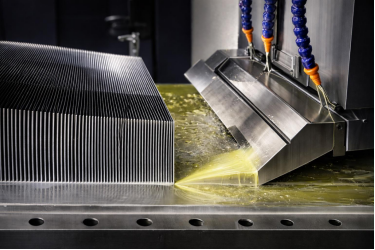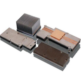
Choosing a heatsink for a high-power, space-constrained assembly is rarely a matter of picking the tallest option off a catalog. When the envelope is tight, the airflow is weak, and the part has to survive vibration, a cold forged pin fin heatsink is often the only geometry that satisfies all three at once. Cold forging is not automatically right either — it is a specific process with specific strengths, limits, and cost profile.
Table of Contents
- What Cold Forging Actually Does to a Cold Forged Heat Sink
- Why the Grain Structure Matters for Cold Forged Heat Sinks
- How to Select Between Extruded, Skived Fin, and Cold Forged Heatsinks
- Cold Forged Heat Sink Technical Specifications and Dimensional Limits
- Materials: High-Purity Aluminum and Hybrid Structures
- Design Considerations for Cold Forged Heat Sink Pin Fins
- Surface Treatment and Secondary Machining
- Quality Control and Certification
- Where Cold Forged Heatsinks Win
- What Engineering Data Is Required for Custom Cold Forged Heatsink Manufacturing
1. What Cold Forging Actually Does to a Cold Forged Heat Sink
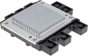
A cold forged aluminum heat sink is made by compressing metal — typically high-purity aluminum or copper — under extreme pressure at room temperature. Because the metal never sees the melting point, forming happens in the solid state, and nearly every property that distinguishes a forged part from a cast or extruded one follows from that.
Working metal in its solid state compacts and refines the grain structure: the elongated, directional grains of an extrusion are broken down into a denser, more uniform structure. Because the metal never reaches its melting point, it does not develop the porosity that degrades thermal performance in a cast part, so a forged part retains conductivity close to that of the parent alloy, with higher strength and tighter repeatability.
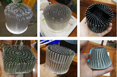
For the designer, the consequence is fin geometry freedom. In die-casting, fins are limited by what molten metal can fill before it freezes and by the draft angles needed for release. In cold forging the material is displaced rather than flowed, so pin fins can be thinner, taller, and more closely spaced. The cold-worked structure also resists vibration and shock better than a cast equivalent.
2. Why the Grain Structure Matters for Cold Forged Heat Sinks
It is worth being precise about the thermal claim, because “forged” is used loosely in this industry — cold forging does not create higher intrinsic conductivity than the alloy you started with.
Cold forging does not change the chemical composition of the aluminum. What it does is preserve the original grain structure and minimize the porosity that degrades thermal performance. That is why the process pairs naturally with high-purity aluminum: a forged high-purity part delivers conductivity close to the alloy’s theoretical maximum, while the same alloy cast rather than forged would lose much of that advantage to porosity and impurities.
The mechanical side follows the same logic. Cold working densifies and work-hardens the material, giving higher yield strength and better fatigue behavior than an as-cast part of the same geometry. That is why forged pin fins can be tall without being fragile.
3. How to Select Between Extruded, Skived Fin, and Cold Forged Heatsinks
The three dominant processes overlap in application but are genuinely different, and choosing between them is usually a question of which constraint you cannot compromise.
| Factor | Cold Forged | Extruded | Skived Fin |
|---|---|---|---|
| Fin cross-section | Solid pin fin | Solid profile fin | Fin from one block |
| Fin thickness | 0.3–3 mm | Die-limited | Very thin |
| Fin pitch | 1.5–10 mm | Die-limited | Set by tool |
| Fin height | Up to 100 mm | Press envelope | Block height |
| Base geometry | Complex, per-tool | Constant | Flat |
| 3D / omnidirectional fins | Yes, net-shape | No (2D only) | Limited (linear) |
| Mechanical strength | Highest | Moderate | Moderate |
| Tooling | Per-part die | Reusable die | Cutting tool |
| Best fit | Density + 3D + rugged | High volume, 2D | Very thin fins, simple base |
Extrusion is unbeatable on cost per part at volume, because one die amortizes across the run; if your geometry is a straight 2D profile at high volume, a forging tool is usually an unnecessary cost. Skiving gets very thin fins because material is removed rather than formed, but it works on a flat block with a simple base and cannot give you a complex one or a three-dimensional fin arrangement.
Cold forging earns its place when you need thin fins and a complex base in the same part, or when fins must interact with airflow from more than one direction. The trade-off is per-part tooling: unit cost at low volume is higher than extrusion, and the design must be stable enough to justify that tool.
4. Cold Forged Heat Sink Technical Specifications and Dimensional Limits
Below are the dimensional and thermal capabilities Goldconn engineers into cold forged heatsinks — achievable ranges rather than a guarantee for every design.
| Parameter | Capability / Range |
|---|---|
| Fin height | Up to 100 mm |
| Fin thickness | 0.3–3 mm |
| Fin pitch | 1.5–10 mm |
| Base thickness | 5–20 mm |
| Maximum overall dimensions | 500 × 500 × 150 mm |
| Thermal resistance | As low as 0.15 °C/W (depending on design) |
| Dimensional tolerance | ±0.05 mm (critical areas) |
| Flatness | 0.01 mm per 100 mm on the mounting interface |
| Surface roughness | Ra 1.6–3.2 μm on the mounting interface |
| Surface finish | Anodizing, nickel plating, custom coatings |
Three of these numbers drive most early decisions. The 0.3–3 mm thickness range defines the density ceiling: finer pins mean more area but also less structural margin if the part is handled roughly. The 500 × 500 × 150 mm envelope is the practical boundary — beyond it, extrusion or a multi-part assembly is generally more viable. And the ±0.05 mm tolerance in critical areas is what makes forged parts viable as mounted thermal interfaces, because a flat, predictable mounting face keeps interface resistance low across a run.
5. Materials: High-Purity Aluminum and Hybrid Structures
Goldconn primarily uses high-purity aluminum — 6061 and 6063 grades — with hybrid structures where maximum conductivity is required: a copper base paired with forged aluminum fins. For reference, 6063 conducts roughly 200 W/m·K, 6061 roughly 167 W/m·K, and C11000 copper roughly 390 W/m·K, which is why copper is placed only where heat first enters.
Hybrid structures exist because conductivity is not equally needed everywhere — heat enters at the mounting interface and travels through the base before spreading into the fins, so copper in the base raises the conductivity of the most critical thermal path while keeping the fins in aluminum. Incoming material is verified by spectral analysis and hardness testing.
6. Design Considerations for Cold Forged Heat Sink Pin Fins
The design stage is where a forged part is either made successful or made expensive to tool. A few decisions carry disproportionate weight.
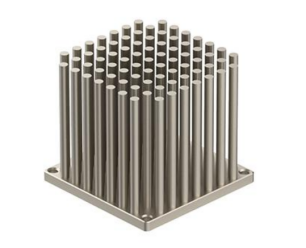
Fin pattern orientation. Forged pin fins can interact with airflow from more than one direction, which is the main reason to choose forging over skiving for an omnidirectional design. If the assembly has a single dominant airflow direction, a simpler directional pattern dissipates heat better — more fins pointed into the actual airstream beats more fins oriented away from it.
Pitch and thickness as a pair. They cannot be optimized independently, because available area is a function of the solid fraction of the fin array. An aggressive pitch forces thickness down to keep airflow passages open; pushing both to their limits produces a part that blocks convection rather than enabling it.
Base thickness and mounting. Base thickness of 5–20 mm should be chosen against how the part is mounted and how much height budget is left for fins.
Simulation before tooling. Because forging requires a dedicated per-part die, an unvalidated design is an expensive risk. CFD and FEA confirm the pattern, pitch, and base geometry before steel is cut.
7. Surface Treatment and Secondary Machining
Forged pin fins are typically delivered with a machined mounting interface, since forging does not produce a finish-quality surface. Precision CNC secondary processing, run on a fleet of 150 CNC machines (3, 4, and 5-axis), machines the mounting interfaces, holes, and special geometry, and this is where the ±0.05 mm tolerance is actually held and verified.
Available treatments include anodizing, nickel plating, and specialized coatings. Anodizing improves corrosion resistance, while its effect on surface emissivity should be evaluated for the application rather than assumed as a thermal benefit; nickel plating is chosen where a harder, more wear-resistant surface is needed. For automotive or harsh-environment use, the treatment decision is also a corrosion decision.
8. Quality Control and Certification
Quality control covers five areas, each tied to a specific failure mode.
- Material purity verification — strict inspection of the aluminum or hybrid material for consistent conductivity between lots
- Dimensional inspection — CMM and gauges verify tolerances on the machined mounting interface; unspecified geometry follows ISO 2768-m and anything affecting thermal contact is called out to ASME Y14.5
- Structural integrity testing — fin root strength and durability validated through thermal cycling, vibration, and mechanical stress
- Thermal performance validation — testing to confirm actual thermal resistance matches design specifications
- Surface finish checks — coating thickness, adhesion, and corrosion resistance, with salt spray to ASTM B117 where the environment calls for it
Goldconn operates under ISO 9001, ISO 14001, ISO 45001, QC 080000, and IATF 16949, with products meeting RoHS and REACH. Certifications are only the baseline; the more telling question is whether a supplier will commit to thermal and mechanical validation on your geometry before cutting steel. Goldconn does: a Beijing Stock Exchange listed OEM (stock code 8383337) since 2004 and holding IATF 16949 since 2009, it runs that validation before the forging die is cut.
9. Where Cold Forged Heatsinks Win
Cold forging is the strongest choice when several of these apply together: high heat flux in a small footprint, where the available fin density is the direct answer; a complex base combined with dense fins, which forging delivers in one part where extrusion would compromise one or the other; omnidirectional airflow, where a forged pin array beats a directional profile; harsh or vibration-exposed environments, where the work-hardened structure has better fatigue behavior than a cast part; and stable high volume once the design is fixed, since the die carries the wear rather than the part.
Where it is not the right answer: a design needing very thin fins on a flat, simple base, where skiving is more efficient, or an envelope beyond 500 × 500 × 150 mm. And because Goldconn runs every process in-house, a part can move from forged to liquid-cooled or bonded without a second supplier.
Those strengths are why forged pin arrays recur in two demanding segments. In an EV powertrain the constraint is packaging space and vibration at once, which is treated in EV power electronics cooling.
In industrial drive equipment the constraint is continuous duty at a defined junction limit, covered under IGBT module and industrial inverter heatsinks.
10. What Engineering Data Is Required for Custom Cold Forged Heatsink Manufacturing
To move a cold forged heatsink from concept to a tooled, production-ready part, send the following.
- Thermal and airflow — heat load in watts, source and target temperature, and the airflow condition (forced CFM or natural convection) from Section 6
- Envelope and mounting — maximum length, width, height, and orientation
- Material preference — high-purity aluminum or a hybrid copper-base structure
- Volume, environment, and drawing — prototype and annual volume, service environment and finish, plus a STEP or PDF file and any existing simulation
A free DFM review and 24-hour quote turnaround are available: contact our engineering team with the data above, and the design can be checked against its manufacturability before committing to a forging tool.
For the broader context across every process, see the custom heatsink design and manufacturing guide.
Frequently Asked Questions
How does cold forging compare to extrusion or die casting thermally?
Cold forging keeps the metal’s original grain structure and maintains conductivity close to that of high-purity aluminum, producing lower thermal resistance than typical extrusion or die-cast parts. It also allows taller, denser fins, because the material is displaced rather than flowed into a die. Exact performance should be confirmed by simulation on your geometry.
What is the minimum fin thickness?
Fin thickness runs from 0.3 mm to 3 mm, with pitch from 1.5 mm to 10 mm and fin height up to 100 mm. Very fine fins maximize area but reduce structural margin, so for vibration-exposed assemblies the realistic minimum is higher than the absolute minimum.
Can cold forged heatsinks be fully customized?
Yes. Fin height, thickness, pitch, overall shape, base geometry, material, and surface treatment are all customizable, with mounting interfaces machined as secondary CNC processing. Prototype timing depends on part complexity and is confirmed in the quotation.
Are cold forged heatsinks suitable for automotive applications?
Yes, and they are particularly well suited. The dense, work-hardened structure provides strong vibration and shock resistance, and Goldconn holds IATF 16949 automotive certification. Cold forged pin fins are commonly specified for battery management systems, inverters, and onboard power electronics.
Is cold forging the same as cold formed?
The terms are often used interchangeably for room-temperature solid-state forming. At Goldconn, cold forged describes components made by compressing high-purity aluminum or copper under high pressure, producing a dense, high-strength part with fine pin fins.
Request a cold forged heatsink quote. Send us the heat load, the fin pattern or STEP file, and the envelope, and our engineering team will return a proposed fin geometry, an alloy recommendation, and a tooling and lead time estimate — typically within two working days. A free design-for-manufacturability review before tooling is the cheapest point at which to change the design.