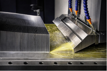
A catalog heatsink that misses your thermal budget, envelope, or cost target has to be replaced with a custom one. This guide covers how such a part is engineered, which process fits which application, what materials and quality controls apply, and how to choose.
Goldconn has made custom heatsinks since 2004. Three plants totalling 58,000 m², 800+ staff, and 300+ machines including 150 CNC machines support OEM programs from first concept through certified volume production.
Table of Contents
- What a Custom Heatsink Is—and When You Need One
- The Goldconn Custom Heatsink Manufacturing Process
- Core Manufacturing Technologies
- Material Selection: Aluminum vs. Copper for Custom Heatsinks
- Engineering Highlights and Precision Capabilities of a Custom Heatsink
- Quality Assurance & Certifications
- Industries We Serve
- How to Choose the Right Custom Heatsink Process
1. What a Custom Heatsink Is—and When You Need One
A heatsink moves heat from a component (a CPU, MOSFET, IGBT, LED array, battery module) into the surrounding air or liquid. A custom one is built around your constraints instead of accepting whatever geometry a stock part offers.
Three levers govern the job: source-to-ambient temperature difference, junction-to-fin conduction resistance, and how well the fins reject heat into the available airflow. Past what an extrusion can deliver, a custom design is the only route.
A stock part stops fitting once two of those levers conflict — watts versus temperature limit, envelope versus mounting space, airflow or coolant versus volume.
2. The Goldconn Custom Heatsink Manufacturing Process
The whole job reduces to one line: a 150 W IGBT module at a 40 °C ambient with a 125 °C junction limit leaves a budget of (125 − 40) / 150 = 0.57 °C/W. If the bolted interface and module case already consume 0.20, the sink must deliver 0.37 — and that number, not the fin count, is what the design has to satisfy. An aluminum sink of this size in still air lands between 0.15 and 0.35 °C/W, so the target is reachable; the same 150 W through a bare bolted interface would need the whole 0.57 °C/W from the joint, which no fin arrangement can deliver. Design the interface first.
Projects move through four stages. Discovery captures the thermal challenge, spatial limits, power, and environment. Thermal analysis runs CFD and FEA before metal is cut, on your geometry or one of ours. Prototyping measures parts before they leave, on a bench with controlled inlet temperature and known airflow, and leak-tests every sealed unit. Manufacturing runs on seven in-house technologies so cost and lead time stay tunable. Prototype timing is confirmed per project once the process route is fixed.
3. Core Manufacturing Technologies
No single process fits every thermal problem. The first table shows where each wins; the second gives the limits that decide whether a design is buildable.
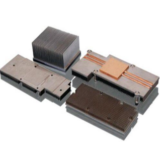
| Process | Best Suited For | Material | Defining Strength |
|---|---|---|---|
| Extruded | High-volume, cost-sensitive air cooling | Al 6061/6063 | Lowest per-unit cost at scale |
| Skived Fin | Maximum density in a tight envelope | Al, Cu | Very thin, tall fins from one block |
| Cold Forged | Complex 3D, omnidirectional fins | Al | Net-shape forming, no machining |
| Liquid Cold Plate | Heat flux beyond air cooling | Al 6061 + Cu C1100 | Internal channels, sealed and leak-tested |
| Heat Pipe / Vapor Chamber | Moving heat from a hotspot | Cu core + Al fins | Rapid, near-isothermal transport |
| Bonded Fin | Hybrid height + base construction | Mixed alloys | Extrusion base + fin stock |
| Die-Cast (integrated) | Enclosure + heatsink as one part | Al ADC12 / A380 | 1250–2000T, no secondary machining |
| Process | Min Fin Thickness | Min Fin Pitch | Max Envelope | Prototype route |
|---|---|---|---|---|
| Extruded | 1.0 mm | 2.0 mm | 200 mm wide, 10–100 mm high, up to 6 m | Existing die, no new tooling |
| Skived Fin | Set by cutter geometry | Must exceed cutter entry geometry | CNC machining envelope | Billet machining, no die |
| Cold Forged | 0.3 mm | 1.5 mm | 500 × 500 × 150 mm | Requires forging die |
| Bonded Fin | 0.2 mm | 1.5 mm | 600 × 600 × 150 mm | Requires die and assembly |
| Liquid Cold Plate | Internal channels | Not applicable | Channel layout and pressure rating | Prototype before tooling |
| Heat Pipe / Vapor Chamber | Pipe dia. 3–8 mm | Not applicable | Pipe arrangement and fin field | Sample before tooling |
| Die-Cast (integrated) | Limited by mold fill and draft | Not applicable | 1250–2000T | 4–8 weeks with tooling |
Two limits eliminate more designs than anything else: below 2.0 mm pitch extrusion is out, and a cold forged part cannot exceed 500 mm in plan — so a 600 mm base moves elsewhere entirely.
Extrusion stays the workhorse where volume drives cost, and our extruded heat sink capability covers profile capability, die design, and volume economics.
Skiving cuts ultra-thin, tall fins from one block, cold forging forms 3D fin geometries in one step, and where air cooling runs out of headroom liquid cold plate fabrication carries coolant through sealed internal channels.
Every route appears in custom heatsink and thermal solutions.
Two of the seven deserve their own treatment, because each changes what the part can physically be. Skived fin heat sinks give the highest density in a tight envelope, cutting thin fins straight from a solid block.
Cold forged heat sinks cover the other case, forming complex three-dimensional fin arrangements in a single piece.
4. Material Selection: Aluminum vs. Copper for Custom Heatsinks
Material choice drives both performance and cost, so it gets decided early. Aluminum (6061 / 6063) is lightweight, economical, and easy to extrude, skive, or forge — the default for air-cooled heatsinks and cold-plate bodies. Copper (C11000) conducts roughly 1.9–2.3× as well, which makes it the choice for the highest-flux spots, cold-plate bases, and chamber cores, at higher weight and cost. Since “aluminum” covers a range, here are the values behind that ratio:
| Material | Conductivity | Density | Cost | Where It Belongs |
|---|---|---|---|---|
| Aluminum 1060 | about 235 W/m·K | 2.70 g/cm³ | Low | Highest-conductivity Al; skived fin fields |
| Aluminum 6063 | about 200 W/m·K | 2.70 g/cm³ | Lowest | Default for fin fields and cold-plate bodies |
| Aluminum 6061 | about 167 W/m·K | 2.70 g/cm³ | Low | Heavier duty parts needing strength |
| Copper C11000 | about 390 W/m·K | 8.96 g/cm³ | Highest | Base plates, cold-plate bases, chamber cores |
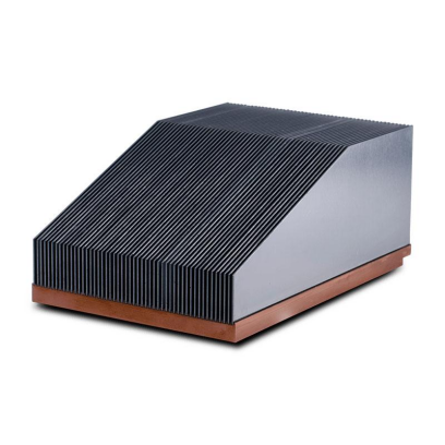
Two numbers in that table decide most hybrid designs. Copper conducts about twice as well as 6063 but is 3.3× as dense, so a solid copper part of the same shape is heavier, more expensive, and faster at spreading heat out of the base. Hence the standard construction: copper base, aluminum fins — the base spreads heat laterally, the fins hold most of the volume and cost.
5. Engineering Highlights and Precision Capabilities of a Custom Heatsink
A few engineering controls separate a heatsink that merely fits from one that performs for years, and each figure is stated with the basis it holds on.
Take flatness. 0.01 mm per 100 mm is not “accurate to a hundredth of a millimeter” but a deviation over a stated datum length: the surface moves at most 10 µm across any 100 mm span, a quarter millimeter on a 40 mm interface. Clamping pressure turns that straight into contact resistance, so it decides whether the device seats across its full area or only at a few high points. The rest follows the same logic: leak-tight cold plate joining, 100% sealed-system validation rather than sampling, and dimensional capability matched to process (±0.01 mm on CNC critical features, ±0.05 mm die-casting, ±0.1 mm across a bonded fin field).
Measurements follow ASME Y14.5 and ISO 2768, alongside customer-specified datums and GD&T callouts. Thermal cycling follows the JESD22-A104 classes, automotive reliability testing MIL-STD-883 Method 520.11, and mill certificates are retained per lot. The figures also have limits: tolerances are measured at room temperature on unloaded parts, so a hot-running design or one with stiffening ribs sees different effective flatness, and thermal figures depend on the test boundary — case-to-ambient is not comparable with one taken across the mounting interface.
6. Quality Assurance & Certifications
Quality is engineered into the part, not inspected on at the end. Goldconn holds ISO 9001, ISO 14001, ISO 45001, and IATF 16949 (automotive quality, held since 2009), with RoHS and QC080000 compliance. Checks run at every stage: material verification by spectral analysis and hardness testing, dimensional inspection on CMM and optical systems, thermal validation by airflow test and thermal imaging, inspection of anodizing and plating, and batch-level traceability.
7. Industries We Serve
Each sector has its own bar, and the constraint that binds is different in every one of them.
Automotive and EV electronics — battery management systems, inverters, and onboard power electronics, built under IATF 16949. The thermal budget and package constraints are set out in EV power electronics cooling.
Telecommunications and 5G — base stations and RF amplifiers running continuously outdoors, where a sealed enclosure limits convection and density does the work instead. See 5G base station and RF amplifier heatsinks.
Data centers and AI infrastructure — high-density liquid cooling for compute and power modules, where heat flux per rack has outgrown air. The design approach is covered in microchannel cold plates for AI servers.
LED lighting — efficient dissipation that extends LED lifespan, which is a thermal resistance problem before it is a brightness one. Covered under LED luminaire and grow light heatsinks.
Industrial automation — motor drives, controllers, and power supplies, where power modules set the duty cycle. See IGBT module and industrial inverter heatsinks.
Consumer electronics — power amplifiers, CPUs, and similar parts, where thin profiles, surface finish, and unit cost drive the design. Treated in consumer electronics and power supply heatsinks.
Solar and energy storage — inverters and storage cabinets working outdoors for a decade or more, where corrosion and long service life matter as much as peak temperature. Described in solar inverter and energy storage heatsinks.
8. How to Choose the Right Custom Heatsink Process
As a rough rule: above about 10,000 pieces a year with a simple 2D profile, choose extrusion, because the die amortizes; below 1,000 pieces with a complex base, choose cold forging. If fin density must exceed what any die holds, choose skived or bonded fin. If the source is small, hot, and unairflowed, choose a liquid cold plate, and if heat must travel a distance inside the product, a heat pipe.
| Primary Constraint | Starting Process | Why |
|---|---|---|
| Lowest unit cost at high volume | Extruded | Continuous fins, minimal per-part cost |
| Maximum density in minimal space | Skived Fin | Thin, tall fins from one block |
| Complex 3D fins, no machining | Cold Forged | Net-shape forming in one step |
| Flux beyond what air can remove | Liquid Cold Plate | Internal channels at the source |
| Heat from a remote hotspot | Heat Pipe | Near-isothermal transport |
| Tall fins on a formed base | Bonded Fin | Hybrid construction |
| Enclosure and sink as one part | Die-Cast | Housing and cooling combined |
Figures mean little without their measurement conditions, so these three applications are written as complete cases and read as reference points, not guarantees. Each turns on a different constraint — interface, economics, envelope. Find the one that binds hardest, and the process follows.
| Application | Duty | Conditions | Construction | Prototype route |
|---|---|---|---|---|
| IGBT module, sealed inverter | 150 W, 125 °C case, 40 °C ambient | Bolted interface, natural convection | Cold forged pin-fin base; interface takes 0.20 °C/W, so the sink is designed to the remaining 0.37 °C/W | Requires forging die |
| LED luminaire, high volume | 60 W, 90 °C case, 25 °C ambient | Simple 2D profile, natural convection, 10,000+ a year | Extruded 6063, anodized; die amortises | Existing die |
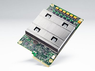
| Accelerator board, 1U tray | 500–700 W per board, rack above 30 kW | Forced air, limited pressure, height restricted | Skived fin array at maximum density the height allows | Billet, no die |
One practical note: because Goldconn runs all seven processes in-house, a design that starts as extruded can shift to forged or liquid-cooled without changing suppliers — useful while a program is still settling.
If the route is still open, contact our engineering team with the drawing and duty conditions; you will get a process recommendation, a free DFM review, and a formal quotation before any tooling is committed.
Frequently Asked Questions
What information does Goldconn need to quote a project?
Heat load and temperature limits, available space, desired material, expected volume, and any 3D models or CAD drawings. Application environment and airflow help sharpen the design.
What are the typical lead times?
Prototype timing is confirmed once the design and process route are final. Production timing is quoted per project based on complexity, process, and volume.
Can Goldconn assist with thermal modeling for an existing design?
Yes. The team uses CFD and FEA to simulate and optimize your geometry, surfacing risks before manufacturing.
What certifications does Goldconn hold?
ISO 9001, ISO 14001, ISO 45001, and IATF 16949 (held since 2009), plus RoHS and QC080000. Goldconn is Beijing Stock Exchange listed (stock code 8383337) and has built custom heatsinks since 2004 — over 20 years.
Request a custom heatsink review. Send us the heat load, the heat source footprint, the envelope, and the airflow situation — by email or by uploading your STEP or PDF drawing — and the engineering team will return a recommended process, a proposed geometry, and a thermal estimate. A free design-for-manufacturability review before tooling is the cheapest point at which to change the design, and typical responses come back within two working days.