Specifying a USB Type-C connector is a long-term reliability decision, not a commodity purchase. The same-looking reversible shell can hide five different pin counts, two mounting philosophies, multiple waterproof grades, and a power range from 15 W to 240 W. The wrong choice shows up as pad peeling after repeated insertions, failed salt-spray qualification, or an EOL redesign when the original part is discontinued. This guide consolidates what hardware engineers and procurement teams should evaluate before releasing a BOM, and links to three deep-dive articles on selection rules, connector comparisons, and manufacturing/supplier qualification.
Table of Contents
- 1. Why Connector Selection Defines Product Reliability
- 2. What a USB Type-C Connector Module Is
- 3. Core Specifications That Determine Fit
- 4. Comparing USB-C Options
- 5. Manufacturing and Supply-Chain Factors
- 6. A Practical Selection Framework
- 7. Common Buyer Mistakes
- 8. Evaluating and Qualifying a Connector Supplier
- Conclusion
- Request a DFM Review and Quote
- Frequently Asked Questions
1. Why Connector Selection Defines Product Reliability
USB Type-C connectors have become the default interface across consumer, industrial, medical, and automotive equipment. The reversible form factor, high-speed data lanes, and USB Power Delivery support are attractive, but they also create a specification trap: two parts can share the same shell and pin count yet differ dramatically in mechanical retention, thermal handling, and signal integrity. The failure modes below are what actually surface after a poor connector decision, and each is more expensive than the original part saving.
- Pad peeling on the PCB—standard surface-mount shells transfer cable-insertion torque to solder joints; under repeated plug/unplug cycles the pads lift and the product fails in the field.
- Liquid ingress in outdoor or medical environments—an unsealed receptacle corrodes contacts after cleaning cycles or rain exposure, even when the rest of the enclosure is IP-rated.
- EMI and signal-integrity surprises—a 24-pin connector routed as USB 2.0 cannot support the 10 Gbps data rate the marketing team expects, forcing a board respin.
- Power-delivery mismatch—quoting a 3 A contact system for a 5 A/240 W charger causes overheating and contact-resistance degradation.
- Longevity risk—a short-life consumer-grade connector cannot survive the 8-year industrial program the customer expects.
2. What a USB Type-C Connector Module Is
A USB Type-C connector module from a manufacturing perspective is a precision electro-mechanical sub-assembly whose every layer influences reliability. The capabilities described on the Goldconn USB Type-C connector page are positioned for OEMs that need more than a catalog part: they need a part that survives mechanical stress, thermal cycling, salt spray, and long supply-chain windows.
Key Components
- Shell—stainless steel or nickel-plated steel; provides EMI shielding, mechanical retention, and the surface the user touches during insertion.
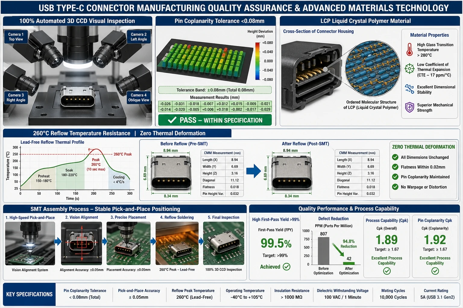
- Housing—high-temperature LCP (liquid crystal polymer) or comparable thermoplastic; must survive reflow without warping.
- Contacts / terminals—copper alloy (C7025) with localized gold plating over nickel; defines current capacity, contact resistance, and wear life.
- Mounting legs—surface-mount tabs or through-hole reflow (THR) legs; determine torque resistance and solder-joint lifetime.
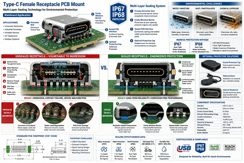
- Sealing—LSR internal sealing and perimeter gaskets for IPX4/IPX8 grades; keeps moisture and dust away from contacts.
- EMI / signal-integrity features—shield continuity, ground fingers, and controlled impedance routing for high-speed lanes.
Target Markets and Buyers
The primary buyers are OEMs and ODMs in consumer electronics, industrial automation, medical devices, smart home/IoT, and audio/video equipment. Within those companies the decision is typically owned by a hardware engineer who validates signal and power budgets, a mechanical engineer who checks retention and sealing, a procurement lead who manages allocation and second-source risk, and a quality engineer who enforces certification requirements.
3. Core Specifications That Determine Fit
The following parameters are the decision-critical specifications. A detailed, specification-by-specification selection logic is covered in the USB Type-C connector selection guide.
Specifications at a Glance
| Parameter | Range / Value | Why It Matters |
|---|---|---|
| Pin count | 6 / 16 / 24 pins | Power-only, USB 2.0 + PD, full USB 3.x/4 data |
| USB standard | USB 2.0 / 3.1 Gen 2 / USB4 | Data rate: 480 Mbps / 10 Gbps / higher |
| Power delivery | Up to 240 W (48 V / 5 A) | Charging and device power budget |
| Mating cycles | 10,000+ cycles | Field life in frequent-use devices |
| Current rating | 3 A or 5 A | Cable and connector thermal load |
| Contact plating | 30 µ” localized gold over nickel | Contact resistance, corrosion, wear |
| Shell material | Stainless steel | EMI shielding and mechanical strength |
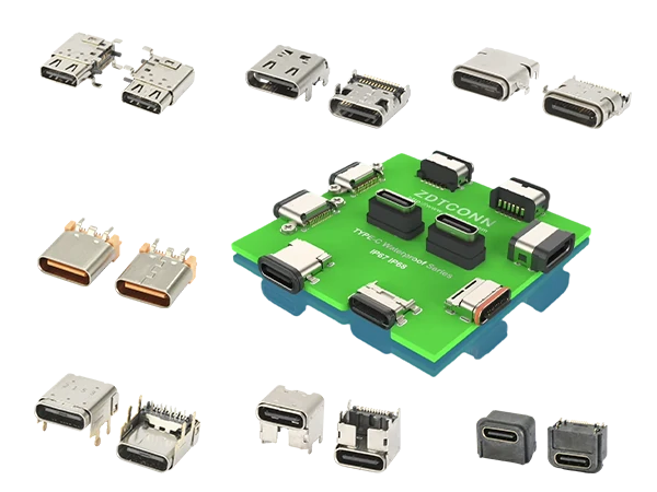
| Mounting | SMT / THR / mid-mount | Retention, torque resistance, board height |
| Waterproof rating | IPX4 / IPX8 | Outdoor, washdown, medical environments |
| Operating temperature | −40°C to +105°C (selected grades) | Automotive and industrial fit |
Pin Count and Data Rate
Goldconn lists 6-pin, 16-pin, and 24-pin female receptacles. The pin count is the first filter: a 6-pin connector is normally power-only or USB 2.0, a 16-pin version supports USB 2.0 plus CC and some power-delivery channels, and a 24-pin full-featured connector carries the SuperSpeed differential pairs needed for USB 3.1 Gen 2 (10 Gbps) and beyond. The headline on the product page also references USB4 solutions, so it is important to confirm which data-rate class is actually quoted in your BOM.
Power Delivery and Thermal Loads
The product page advertises up to 240 W (48 V / 5 A). At the same time, the FAQ references USB PD 3.0 up to 100 W. This difference is not a contradiction: 100 W is the legacy PD 3.0 upper limit, while 240 W is the Extended Power Range (EPR) profile. The engineering check is which PD contract the supplier guarantees, because contact plating, terminal alloy, and housing material must all be rated for the selected power class. Goldconn specifies C7025 copper alloy terminals and 30 µ” localized gold plating to manage these thermal and wear conditions.
Mechanical Retention and Mounting
For connectors exposed to frequent insertion or cable-pull loads, through-hole reflow (THR) mounting legs provide far better board retention than surface-mount tabs alone. Goldconn uses a 6-leg THR design combined with 360° laser seamless welding, claiming a 40% increase in torque resistance and elimination of pad peeling. This is a meaningful differentiator in industrial handhelds, automotive consoles, and medical carts where cables are stressed daily.
4. Comparing USB-C Options
Not every USB-C connector solves the same problem. A smartphone charging-only port, an industrial HMI data port, and an automotive diagnostics port all use Type-C shells but need different internal architectures. The trade-offs between pin count, mounting style, waterproofing, and plating are covered in detail in the USB Type-C connector comparison.
Quick Decision Table
| Application Need | Recommended Configuration | Key Risk If Wrong |
|---|---|---|
| Power-only charging, cost-sensitive | 6-pin, SMT, 3 A | Cannot support data later |
| USB 2.0 + PD charging | 16-pin, SMT/THR, 3–5 A | Insufficient pins for high-speed lanes |
| USB 3.1 Gen 2 data + 240 W | 24-pin, THR, 5 A, IPX8 | Thermal runaway, signal loss |
| Outdoor / washdown / medical | Sealed receptacle, IPX8, THR | Corrosion, warranty returns |
| High-vibration automotive | 6-leg THR + laser-welded shell | Pad peeling, intermittent contact |
5. Manufacturing and Supply-Chain Factors
A connector drawing approved for prototyping is only half the battle. Stable volume production depends on coplanarity control, reflow compatibility, automated inspection, and a supplier who can sustain the program for years. The manufacturing-side decisions—including DFM, tooling, inspection, and longevity programs—are covered in the USB Type-C connector manufacturing and supplier selection article.
Coplanarity and SMT Yield
Micro-pitch Type-C terminals must be coplanar within tight limits to avoid open or shorted solder joints after reflow. Goldconn states pin coplanarity is held strictly under 0.08 mm using 3D CCD vision systems. This is not a marketing number: poor coplanarity is one of the leading causes of first-pass yield loss in connector assembly.
Sealing and IP Ratings
LSR internal sealing and perimeter gasket systems are used to achieve IPX4 splashproof and IPX8 submersible protection. The sealing design must be validated with the specific mating plug and cable gland, because the connector alone cannot make a system waterproof without enclosure integration.
6. A Practical Selection Framework
Use this sequence when moving from a product requirement to a connector specification:
- Define data and power budgets separately. Do not assume all USB-C ports support the same USB standard or PD profile.
- Choose pin count based on the required signal lanes. Power-only or USB 2.0 applications can use 6-pin or 16-pin; full USB 3.x/4 requires 24-pin.
- Select mounting style based on mechanical load. Frequent insertion, vibration, or cable-pull load should drive THR or 6-leg THR.
- Specify sealing only when the end product is sealed and validated as a system. IPX8 connectors in an unsealed enclosure provide limited value.
- Confirm current rating and plating at the quoted power level. 240 W EPR needs 5 A contacts and thermally capable housing material.
- Lock the supplier qualification and longevity plan before mass production. An 8-year program without a PCN/BOM-lock policy is risky.
7. Common Buyer Mistakes
- Treating Type-C as one standard—USB-C is a connector form factor, not a guaranteed data rate or power level.
- Specifying waterproofing without system validation—the port, cable, enclosure, and gasket must be tested together.
- Ignoring mounting torque—SMT-only shells are fine for light-use consumer devices but risky in industrial or automotive.
- Assuming 100 W and 240 W are interchangeable—they require different contact, housing, and cable systems.
- Skipping the supplier audit—coplanarity control, reflow profile, and traceability cannot be verified from a datasheet.
- Neglecting the plug side—a rugged receptacle paired with a non-rated cable still fails in the field.
8. Evaluating and Qualifying a Connector Supplier
The right supplier reduces long-term risk more than the lowest unit price. Goldconn notes it is a Beijing Stock Exchange-listed manufacturer (Stock Code 8383337) with ISO9001, ISO14001, IATF16949, and TID certifications. It offers an 8-year longevity program, free samples up to 100 units, and DFM support. When qualifying any connector supplier, request the following evidence:
- Certification scope—ISO9001 and IATF16949 certificates with the connector product scope clearly listed.
- USB-IF TID listing—confirms the specific connector model has passed USB compliance testing.
- Coplanarity and inspection data—Cpk data for pin coplanarity and 3D CCD inspection coverage.
- Reliability test reports—insertion/extraction life, salt spray, temperature cycling, and vibration results.
- Traceability—lot/batch records for raw material, plating, molding, and assembly.
- Longevity and PCN policy—documented 8-year program and change-notification procedure.
Conclusion
A USB Type-C connector selection is a stack of electrical, mechanical, environmental, and supply-chain decisions. Start by separating the data-rate, power, and mechanical requirements; then match pin count, mounting, sealing, and plating to the application. Finally, qualify the supplier on coplanarity control, testing depth, and longevity commitment rather than price alone. The articles linked below provide deeper guidance on each phase of the decision.
Request a DFM Review and Quote
Send us your application requirements—data rate, power budget, mounting constraints, waterproof grade, and annual volume—and our engineering team will return a DFM review, sample plan, and project quotation within 3–5 business days. You can also review the full USB Type-C connector product range to identify the starting point for your design.
Frequently Asked Questions
What is the difference between 6-pin, 16-pin, and 24-pin Type-C connectors?
6-pin connectors typically support only power or USB 2.0 plus configuration channels. 16-pin versions add power-delivery capability and sometimes limited USB 2.0 signaling. 24-pin connectors carry the full set of SuperSpeed differential pairs required for USB 3.1 Gen 2 (10 Gbps) and higher data rates.
Can a Type-C connector really support 240 W charging?
Yes, but only when the connector, cable, and power controller all support USB PD Extended Power Range (EPR) at 48 V and 5 A. Standard USB PD 3.0 tops out at 100 W, so the BOM and cable assembly must be specified to the higher EPR profile.
What does IPX8 mean for a USB-C receptacle?
IPX8 means the connector can withstand continuous immersion in water under conditions specified by the manufacturer, typically a defined depth and time. System-level waterproofing still depends on enclosure sealing, cable gland design, and plug mating.
Why is pin coplanarity important?
Pin coplanarity ensures all terminals contact the PCB pads evenly during reflow. Poor coplanarity causes open joints or solder bridges, leading to first-pass yield loss and latent field failures.
Is THR better than SMT for Type-C connectors?
THR provides stronger mechanical anchoring to the PCB and is preferred for high-vibration, high-insertion, or cable-pull applications. SMT is lower profile and sufficient for light-use consumer devices where board space is critical.
What certifications should I look for in a Type-C supplier?
Look for ISO9001 quality management, IATF16949 automotive quality, USB-IF TID certification for the specific connector model, and RoHS/REACH environmental compliance.
How many free samples does Goldconn provide?
The company offers up to 100 free Type-C male or female connector samples for customer testing and validation before mass production.
How long is the typical industrial supply program?
Goldconn offers a minimum 8-year longevity program for industrial clients, backed by BOM locking and product-change-notification (PCN) procedures to avoid unexpected redesigns.